TL;DR: We solved the “Ethernet from Above” hardware challenge at Pwn2Win CTF, which went unsolved during the main event. This challenge required reversing an FPGA design given only its binary configuration (bitfile). The organizers left it open as a bonus afterwards, so Daniel (@____esc__) and I collaborated to solve this challenge and claim the offered prize of 1 XMR. Read on to see how we did it!
Problem Description
The ethernet from above
- Solves: 0
- Score: 500
- Tags: hardware, rev
Most of the obscure activities conducted by the Rhiza government are carried out on the continent to stay out of the Island’s commoners’ eyes and prevent information leakage. However, buildings on the Island storing potentially compromising material, such as the human genetics centre, have a rigid access control system.
Laura managed to compromise some computers in the government lab that develops this system. When analyzing the project, she found that the weakest point seems to be the electronic board that checks whether the access code to enter the buildings is correct. There is nothing special about the board itself: it is a Colorlight 5A-75B V7.0 board that, apparently, could be found very easily before the war. What is interesting is the bitfile programmed to the board, which is developed by the government lab.
Laura got access to the bitfile that the lab is testing. The specifications accompanying the bitfile state that the board can be accessed at 200.18.104.100 on UDP port 6000 after being connected to the network. Upon receiving the correct access code, it returns a datagram beginning with OK. Otherwise, it returns NOK. The project is apparently based on a customized version of LiteEth. Still, Laura was unable to gain access to the complete source code.
Reverse engineer the bitfile to find out which access code is accepted by the board.
Curiosity: If you don’t have a Colorlight and want to see the bitfile working, you can submit it to Rhiza’s test infrastructure. But it probably won’t help you to solve the challenge. You really need to reverse engineer the bitfile.
Files
The provided package contains only a single file: ethernetfromabove.bit, SHA256 8284338c996fa44fc98826110cc9fecde83cb9b31768f2f46b83cb7228c71283.
Introduction
We’re given a “bitfile” programmed to a particular board, a “Colorlight 5A-75B V7.0”. A quick internet search leads us to a GitHub post (https://github.com/q3k/chubby75/blob/master/5a-75b/hardware_V7.0.md) describing the hardware. The key components are:
- Lattice ECP5
LFE5U-25F-6BG256C - 2x Broadcom
B50612DGigabit Ethernet PHYs
The board additionally contains some SDRAM modules, SPI flash and a bunch of 5V level translators, which were not used in the provided design.
A lot of boards that I’m familiar with would come with embedded CPUs at the core of the design, such as an Atmel AVR or ARM CPU. But, this board does not come with a CPU. Instead, the heart of the Colorlight 5A-75B is the Lattice ECP5, which is an FPGA according to the product page.
What is an FPGA?
An FPGA, or “field-programmable gate array”, is a kind of programmable circuit. In a traditional electronic design, such as an integrated circuit or printed circuit board, the various components are connected with fixed wires to each other and arranged in a preset configuration. A CPU, with memory, may be used to provide dynamic behaviour. An FPGA, by contrast, provides a large array of programmable logic units - along with other kinds of supporting units for functions like I/O and memory - and crucially allows their connections and configurations to be arbitrarily configured.
Below, you can see the block layout of the Lattice iCE40 HX1K, a very small but illustrative FPGA.
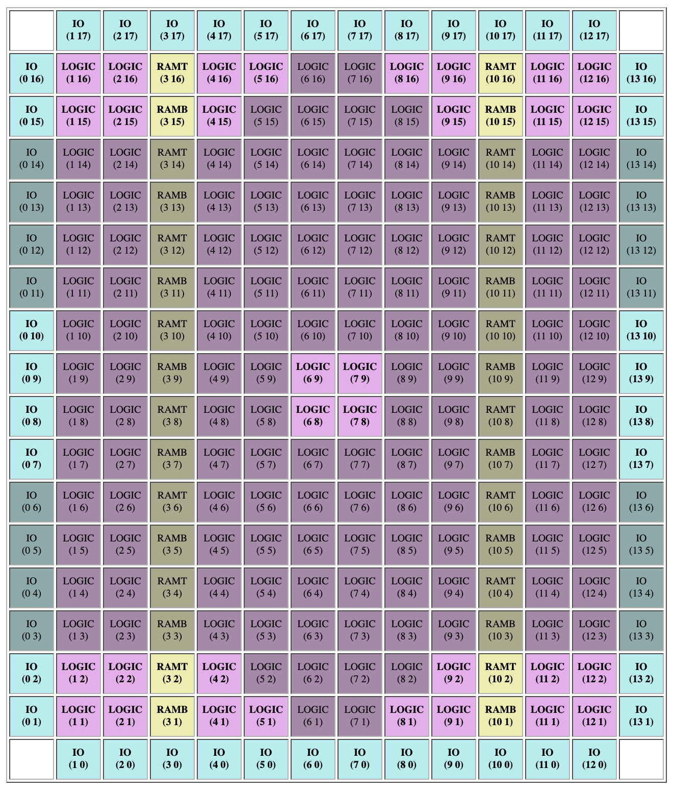
As you can see, the FPGA consists of a large number of “tiles”: IO tiles, LOGIC tiles and RAM tiles. I/O tiles handle input/output on the external pins of the FPGA, to interface with external devices (for example, ethernet adapters, audio/video devices, clock signals, LEDs and displays, sensors, etc.); LOGIC tiles handle digital logic; and RAM tiles provide pre-built data storage capabilities.
I/O tiles exist to support the various needs of external devices, and are responsible for handling things like I/O voltages (e.g. 1.8V, 3.3V), I/O standards (e.g. double data rate (DDR), differential signals (LVDS), etc.), clock generation (PLLs, clock multiplication/division, clock skew and phase compensation, etc.). RAM provides dedicated data storage capabilities; while RAM can be implemented just using LOGIC tiles, it would be much less efficient, so having dedicated RAM is beneficial for reducing design complexity.
LOGIC tiles typically contain two types of components: lookup tables (LUTs) and flip-flops (FFs). Lookup tables are used to implement combinatorial logic: they take some number of binary inputs (typically 3-4 inputs) and produce a single binary output based on a configurable table which provides the binary output for each combination of inputs. For example, a lookup table with inputs a, b, c could compute the function (a & b) | c by using the following table:
a   b   c   a & b | c
0	0	0	0
0	0	1	1
0	1	0	0
0	1	1	1
1	0	0	0
1	0	1	1
1	1	0	1
1	1	1	1
Compactly, this would be encoded as the binary string 11101010 (with the most significant bit corresponding to inputs 1, 1, 1 and the least significant bit corresponding to inputs 0, 0, 0). LUTs can very concisely implement any boolean function of their inputs, and by chaining together LUTs, arbitrarily complex boolean functions can be implemented.
Flip-flops are used to implement sequential logic. Whereas the output of a LUT always reflects its inputs (after a negligible propagation delay), a flip-flop has a clock input and only updates its output when the clock changes. This provides a form of memory, and allows the implementation of stateful constructs such as finite state machines.
Almost any practical digital logic circuit can be expressed in terms of combinatorial and sequential logic, and these in turn can be implemented on top of LUTs and FFs, thereby making FPGAs able to effectively universally express any digital logic.
The other key part of the FPGA is placement and routing (place-and-route for short), which is responsible for determining ideal positions of tiles and connecting the various inputs and outputs of the tiles together as efficiently as possible. Rather than fixed wires running between components, virtually every input to every component is driven by a mux which can be configured to connect to one of several different potential inputs. Those potential inputs are connected to the neighbours of each tile. Tiles also typically have dedicated routing muxes without logical components attached, which are used to carry signals across multiple tiles. Finally, there’s a clock routing network that carries clock signals from the I/O tiles through to every single tile in the device, arranged in a special tree structure (an H tree) which ensures that the clocks arrive at every component at the exact same time.
This online floorplan viewer (https://knielsen.github.io/ice40_viewer/ice40_viewer.html) allows you to actually see the various routing connections and configurations of a typical FPGA. You can select a design on the right side to see how that design is implemented a - the example “icestick” for example is implemented on an iCE40 HX1K (pictured above).
Reversing
For various reasons, manufacturers of FPGAs typically do not disclose every little detail of their architecture. For example, the format of the bitstream, which provides the complete FPGA configuration (containing the settings for every LUT, FF, and mux in the FPGA), is usually not documented in detail. As such, hobbyists have turned to reverse engineering to figure out these details. Once these details are completely understood, it then becomes possible to generate bitstreams for these FPGAs using open-source software instead of the proprietary software provided by the manufacturer. Some prominent reverse engineering efforts include Project IceStorm for the Lattice iCE40 chips and Project Trellis for the Lattice ECP5 chips (including the LFE5U-25F used in this CTF challenge). The results of these projects have been used to provide support for their respective chips in the Yosys+nextpnr open-source synthesis suite.
The usual flow for producing an FPGA bitstream file begins with the hardware description in an event-driven language like Verilog or VHDL. This hardware description specifies what the hardware should do (at the level of e.g. “on clock signal, update these wires”). There are also higher-level languages like Chisel, Clash or Migen with a heavier focus on mapping the combinatorial nature of hardware design using software engineering principles (i.e. object-oriented or functional programming) and these languages can typically be compiled to Verilog or VHDL. The synthesis software (e.g. Yosys) then uses this hardware description to produce a concrete list of the LUTs, FFs and other components that need to be instantiated to realize the description. Place-and-route software (e.g. nextpnr) then figures out where to put everything to optimize the electrical behaviour and performance of the design for a given FPGA, assigning the various configurations to tiles, routing connections, and finally generating an appropriate bitstream file.
In this challenge, we’re interested in going the other way: we have a bitstream, and we’d like to figure out how it corresponds with a more abstract hardware description. Luckily, Project Trellis has documented the bitstream format, and even more luckily, they’ve written an entire library (libtrellis, accessible via Python bindings as pytrellis) for interacting with the bitstream format. However, Project Trellis lacks some of the fancy tools that the related Project IceStorm has, such as a floorplan visualizer and a bitstream-to-verilog converter. As such, we’re going to have to build a lot of the tooling we need ourselves.
This challenge uses a Lattice ECP5 LFE5U-25F-6BG256C, which belongs to the Lattice ECP5 family. This particular chip features over 3000 programmable logic tiles (“PLC2”), each of which contains 4 “slices”. The slices are mostly independent; each slice has two four-bit LUTs and two flip-flops, for a total of over 24,000 LUTs. A full floorplan of all the tiles in the chip can be found in the Project Trellis database: http://yosyshq.net/prjtrellis-db/ECP5/LFE5U-25F/index.html.
Step 1 is to get a human-readable description of the provided bitstream so we have some idea of what we’re dealing with. We use the ecpunpack program from Project Trellis: ecpunpack ethernetfromabove.bit ethernetfromabove.config. This produces an 80,000-line configuration file, which contains the configuration for every single tile and its connections to other tiles. For example, here’s the configuration for just one logic tile:
.tile R17C20:PLC2
arc: A7 N1_V01N0101
arc: B2 H00L0000
arc: B3 H01W0100
arc: B4 V02N0701
arc: B5 V01S0000
arc: B6 E1_H02W0301
arc: B7 E1_H02W0101
arc: C2 V02N0401
arc: C3 N1_V01N0001
arc: C4 F6
arc: C5 V00T0000
arc: C6 V02N0201
arc: C7 H02W0401
arc: CE0 H00L0100
arc: CE1 H00R0000
arc: CE2 V02N0601
arc: CLK0 G_HPBX0000
arc: D2 V00T0100
arc: D3 V00T0100
arc: D4 H00R0100
arc: D5 H00R0100
arc: D6 H02W0001
arc: D7 V02S0601
arc: E1_H02E0101 S3_V06N0103
arc: E1_H02E0601 E1_H01W0000
arc: H00L0000 N1_V02S0201
arc: H00L0100 H02E0301
arc: H00R0000 N1_V02S0401
arc: H00R0100 H02W0501
arc: H01W0000 Q0
arc: H01W0100 Q2
arc: M0 V00B0000
arc: MUXCLK0 CLK0
arc: MUXCLK1 CLK0
arc: MUXCLK2 CLK0
arc: N1_V01N0001 F7
arc: N1_V01N0101 F6
arc: N1_V02N0001 E1_H02W0001
arc: N1_V02N0101 E1_H01W0100
arc: N1_V02N0301 Q3
arc: N1_V02N0401 N1_V01S0000
arc: N1_V02N0701 E1_H01W0100
arc: N3_V06N0003 Q0
arc: N3_V06N0303 Q5
arc: V00B0000 V02N0201
arc: V00T0000 H02W0201
arc: V00T0100 N1_V02S0501
arc: V01S0000 Q4
arc: V01S0100 Q0
arc: W1_H02W0401 S1_V02N0401
arc: W1_H02W0501 V01N0101
word: SLICEA.K0.INIT 0000000000000000
word: SLICEA.K1.INIT 0000000000000000
word: SLICEB.K0.INIT 1100110000001111
word: SLICEB.K1.INIT 1100110000001111
word: SLICEC.K0.INIT 1100110000001111
word: SLICEC.K1.INIT 1100110000001111
word: SLICED.K0.INIT 0000000000111111
word: SLICED.K1.INIT 0000101110111011
enum: SLICEA.A0MUX 1
enum: SLICEA.A1MUX 1
enum: SLICEA.B0MUX 1
enum: SLICEA.B1MUX 1
enum: SLICEA.C0MUX 1
enum: SLICEA.C1MUX 1
enum: SLICEA.D0MUX 1
enum: SLICEA.D1MUX 1
enum: SLICEA.GSR DISABLED
enum: SLICEA.REG0.REGSET RESET
enum: SLICEA.REG0.SD 0
enum: SLICEA.REG1.REGSET RESET
enum: SLICEA.REG1.SD 0
enum: SLICEB.A0MUX 1
enum: SLICEB.A1MUX 1
enum: SLICEB.GSR DISABLED
enum: SLICEB.REG0.REGSET RESET
enum: SLICEB.REG1.REGSET RESET
enum: SLICEC.A0MUX 1
enum: SLICEC.A1MUX 1
enum: SLICEC.GSR DISABLED
enum: SLICEC.REG0.REGSET RESET
enum: SLICEC.REG1.REGSET RESET
enum: SLICED.A0MUX 1
enum: SLICED.CEMUX 1
enum: SLICED.GSR DISABLED
enum: SLICED.REG0.REGSET RESET
enum: SLICED.REG0.SD 0
enum: SLICED.REG1.REGSET RESET
enum: SLICED.REG1.SD 0
Here, arc means the configuration of a MUX (indicating which incoming wires are being connected to which outgoing wires), word means the configuration of a LUT, and enum means other configuration bits. For example, SLICEB.A0MUX 1 means that the A0 input to slice B is connected to a constant 1 signal instead of an input wire, and SLICED.REG0.REGSET RESET means that flip-flop 0 in slice D will start in the RESET state (i.e. with a digital zero). Default arcs, words and enums are not shown (the Project Trellis Database provides the defaults, e.g. for the PLC2 tile, http://yosyshq.net/prjtrellis-db/ECP5/tilehtml/PLC2.html, we can see that A0MUX defaults to A0 and REGSET defaults to SET).
Arcs are specified as mux input pairs, where the first element specifies the name of the mux, and the second element specifies what input the mux is connected to (which might itself be the output of another mux). So, for example, arc: C4 F6 means that input C4 is driven by the output F6. A slightly more complicated example is arc: V01S0000 Q4 and arc: B5 V01S0000, which indicates that output Q4 is connected to input B5 via the V01S0000 mux. It gets much more complex, though: the E1_, N3_, S3_ etc. muxes control wires which travel between tiles - some jump to tiles as far as 6 tiles away.
Although this configuration file is at least human-readable, it doesn’t give much insight into the connections between components and we don’t really care about how a connection is made so much as what tiles are connected. We’ll have to extract out the actual connection graph to get anything useful.
Project Trellis provides a pytrellis module which wraps their C++ API and makes it relatively nice to use. Although the API isn’t that well documented, there are some example Python scripts in the repo, and for lingering questions I could always read the C++ code itself. However, to speed up development, I also decided it would be appropriate to create a Python type stub file for the library so I can get autocomplete and proper type checking. I initially used pybind11-stubgen but it had quite a few issues (including syntax errors in the output from unconverted C++ syntax), so I switched to mypy.stubgen and got much better output. I did a decent amount of manual fixup, including generifying all of the vector and map classes, and wound up with a decently usable pytrellis.pyi type stub file for development.
The hardest parts of developing the graph extraction process were figuring out how to use the API and dealing with “fixed” connections. Fixed connections are arcs which are not configurable. Some of these arcs connect wires to the actual input pins of the logic components such as slices and I/O modules (referred to as Basic Element of Logic, or BELs); for example, on PLC2 logic tiles, the B1 input pin on the SLICEC BEL is connected to the B5_SLICE wire, which is in turn connected to the B5 mux output, all via fixed wires. Other fixed connections run between BELs, and some even run between BELs on adjacent tiles (for supporting things like carry chains). If all fixed arcs were integrated into the connection graph, it would bloat the graph considerably - indeed, practically every slice is connected to every other slice through fixed connections. Instead, to avoid blow up, I only include fixed connections if the BELs they ultimately connect to have any configured arcs.
It took a couple of days to throw together a working connection graph extractor; here it is:
graph.py
from collections import defaultdict
from dataclasses import dataclass, field
from typing import ClassVar, Dict, List, Optional, Set
import pytrellis
import os


def init_renames(filename: str) -> Dict[str, str]:
    import json

    res: Dict[str, str] = {}
    with open(filename, "r") as inf:
        data = json.load(inf)
        for pin_name, pin_data in data.items():
            res["R{row}C{col}_PIO{pio}".format(**pin_data)] = f"{pin_name}_PIO"
            res["R{row}C{col}_IOLOGIC{pio}".format(**pin_data)] = f"{pin_name}_IOLOGIC"

    return res


# iodb_CABGA256.json is value of the packages.CABGA256 key from https://github.com/YosysHQ/prjtrellis-db/blob/master/ECP5/LFE5U-25F/iodb.json
mod_renames = init_renames(os.path.join(os.path.dirname(__file__), "iodb_CABGA256.json"))


@dataclass(eq=True, order=True, frozen=True)
class Ident:
    """ An identifier in the routing graph """

    # place label first so we sort by identifier
    label: str = field(compare=False)
    # Idents are unique by ID so we only need to compare IDs
    id: int = field(repr=False)
    _cache: ClassVar[Dict[int, "Ident"]] = {}

    @classmethod
    def from_id(cls, rgraph: pytrellis.RoutingGraph, id: int) -> "Ident":
        if id in cls._cache:
            return cls._cache[id]
        inst = Ident(rgraph.to_str(id), id)
        cls._cache[id] = inst
        return inst

    @classmethod
    def from_label(cls, rgraph: pytrellis.RoutingGraph, label: str) -> "Ident":
        return cls.from_id(rgraph, rgraph.ident(label))

    def __str__(self) -> str:
        return self.label


@dataclass(eq=True, order=True, frozen=True)
class Node:
    """ A node in the routing graph - either a wire or a BEL pin """

    # put y first so we sort by row, then column
    y: int
    x: int
    id: Ident
    pin: Optional[Ident] = None

    @property
    def loc(self) -> pytrellis.Location:
        return pytrellis.Location(self.x, self.y)

    @property
    def mod_name(self) -> str:
        res = f"R{self.y}C{self.x}_{self.name}"
        return mod_renames.get(res, res)

    @property
    def name(self) -> str:
        return self.id.label

    @property
    def pin_name(self) -> str:
        if self.pin is None:
            return ""
        return self.pin.label

    def __str__(self) -> str:
        res = self.mod_name
        if self.pin is not None:
            res += "$" + self.pin_name
        return res


EdgeMap = Dict[Node, Set[Node]]


@dataclass
class Component:
    graph: "DirectedGraph"
    nodes: Set[Node] = field(default_factory=set)

    def get_roots(self) -> Set[Node]:
        roots = set()
        seen: Dict[Node, int] = {}

        def visit(node: Node) -> None:
            if node in seen:
                if seen[node] == 0:
                    print(f"Warning: node {node} is part of a cycle!")
                return
            seen[node] = 0
            if not self.graph.edges_rev[node]:
                roots.add(node)
            else:
                for x in self.graph.edges_rev[node]:
                    visit(x)
            seen[node] = 1

        for x in self.nodes:
            visit(x)

        return roots

    def get_leaves(self) -> Set[Node]:
        leaves = set()
        seen: Dict[Node, int] = {}

        def visit(node: Node) -> None:
            if node in seen:
                if seen[node] == 0:
                    print(f"Warning: node {node} is part of a cycle!")
                return
            seen[node] = 0
            if not self.graph.edges_fwd[node]:
                leaves.add(node)
            else:
                for x in self.graph.edges_fwd[node]:
                    visit(x)
            seen[node] = 1

        for x in self.nodes:
            visit(x)

        return leaves


@dataclass
class DirectedGraph:
    """ A directed graph of Nodes. """

    edges_fwd: EdgeMap = field(default_factory=lambda: defaultdict(set))
    edges_rev: EdgeMap = field(default_factory=lambda: defaultdict(set))

    def add_edge(self, source: Node, sink: Node) -> None:
        self.edges_fwd[source].add(sink)
        self.edges_rev[sink].add(source)

    def get_components(self) -> List[Component]:
        seen: Set[Node] = set()

        def visit(node: Node, component: Component) -> None:
            if node in seen:
                return
            seen.add(node)

            component.nodes.add(node)
            if node in self.edges_fwd:
                for x in self.edges_fwd[node]:
                    visit(x, component)
            if node in self.edges_rev:
                for x in self.edges_rev[node]:
                    visit(x, component)

        components: List[Component] = []
        for edges in (self.edges_rev, self.edges_fwd):
            for node in edges:
                if node in seen:
                    continue
                component = Component(self)
                visit(node, component)
                components.append(component)

        return components
gen_graph.py
import pickle
import sys
from collections import defaultdict
from functools import lru_cache
from typing import Callable, Dict, List, Set, Tuple

import pytrellis
from graph import DirectedGraph, Ident, Node

pytrellis.load_database("usr/local/share/trellis/database/")
bitstream = pytrellis.Bitstream.read_bit(sys.argv[1])
chip = bitstream.deserialise_chip()
rgraph = chip.get_routing_graph()


def get_tile_config(chip: pytrellis.Chip, tile: pytrellis.Tile) -> pytrellis.TileConfig:
    """ Get TileConfig for a given tile on the board """
    locator = pytrellis.TileLocator(chip.info.family, chip.info.name, tile.info.type)
    tilebitdb = pytrellis.get_tile_bitdata(locator)
    return tilebitdb.tile_cram_to_config(tile.cram)


def get_tile_location(tile: pytrellis.Tile) -> pytrellis.Location:
    """ Get the location of a tile suitable for lookup in the RoutingGraph """
    rc = tile.info.get_row_col()
    row, col = rc.first, rc.second
    return pytrellis.Location(col, row)


@lru_cache(None)
def get_zero_bit_arcs(chip: pytrellis.Chip, tiletype: str) -> Dict[str, List[str]]:
    """Get configurable zero-bit arcs from the given tile.

    tile_cram_to_config ignores zero-bit arcs when generating the TileConfig,
    which means that if all bits are unset for a given mux, no connection is
    generated at all."""
    locator = pytrellis.TileLocator(chip.info.family, chip.info.name, tiletype)
    tilebitdb = pytrellis.get_tile_bitdata(locator)
    arcs: Dict[str, List[str]] = defaultdict(list)
    for sink in tilebitdb.get_sinks():
        mux_data = tilebitdb.get_mux_data_for_sink(sink)
        for arc_name, arc_data in mux_data.arcs.items():
            if len(arc_data.bits.bits) == 0:
                arcs[sink].append(arc_name)
    return arcs


def bel_to_node(pos: Tuple[pytrellis.RoutingId, int]) -> Node:
    rid, bel_pin = pos
    id = Ident.from_id(rgraph, rid.id)
    pin = Ident.from_id(rgraph, bel_pin)
    return Node(x=rid.loc.x, y=rid.loc.y, id=id, pin=pin)


def wire_to_node(rid: pytrellis.RoutingId) -> Node:
    id = Ident.from_id(rgraph, rid.id)
    return Node(x=rid.loc.x, y=rid.loc.y, id=id)


config_graph = DirectedGraph()
loc_to_tile: Dict[Tuple[int, int], List[pytrellis.Tile]] = defaultdict(list)

for tilename, tile in chip.tiles.items():
    tilecfg = get_tile_config(chip, tile)
    tileloc = get_tile_location(tile)
    loc_to_tile[tileloc.x, tileloc.y].append(tile)
    rtile = rgraph.tiles[tileloc]
    for arc in tilecfg.carcs:
        rarc = rtile.arcs[rgraph.ident(f"{arc.source}->{arc.sink}")]
        sourcenode = wire_to_node(rarc.source)
        sinknode = wire_to_node(rarc.sink)
        config_graph.add_edge(sourcenode, sinknode)


# Expand configuration arcs to include BEL connections and zero-bit arcs
arc_graph = DirectedGraph()
nodes_seen: Set[Node] = set()


def visit_node(node: Node, bel_func: Callable[[Node], None]) -> None:
    """ Add unconfigurable or implicit arcs to the given node """
    if node in nodes_seen:
        return
    nodes_seen.add(node)

    try:
        rtile = rgraph.tiles[node.loc]
        rwire = rtile.wires[node.id.id]
    except KeyError:
        # there's a handful of troublesome cases which are outside of my control.
        # Example: R0C31_G_ULDDRDEL does not exist; it's actually supposed to be the "fixed"
        # connection G_ULDDRDEL=>DDRDEL but G_ULDDRDEL is not in the same tile.
        print(f"Error: failed to find node {str(node)}", file=sys.stderr)
        return

    if node not in config_graph.edges_rev:
        # Not configured - possible zero-bit configuration
        for tile in loc_to_tile[node.x, node.y]:
            arcs = get_zero_bit_arcs(chip, tile.info.type)
            sources = arcs.get(node.id.label, [])
            if not sources:
                continue
            for source in sources:
                sourceid = Ident.from_label(rgraph, source)
                sourcenode = Node(x=node.x, y=node.y, id=sourceid)
                arc_graph.add_edge(sourcenode, node)
                visit_node(sourcenode, bel_func)

    # Add fixed connections
    for bel in rwire.belsUphill:
        arc_graph.add_edge(bel_to_node(bel), node)
        bel_func(wire_to_node(bel[0]))
    for bel in rwire.belsDownhill:
        arc_graph.add_edge(node, bel_to_node(bel))
        bel_func(wire_to_node(bel[0]))
    for routes in [rwire.uphill, rwire.downhill]:
        for rarcrid in routes:
            rarcname = rgraph.to_str(rarcrid.id)
            if "=>" in rarcname:
                # => means a fixed (unconfigurable) connection
                rarc = rgraph.tiles[rarcrid.loc].arcs[rarcrid.id]
                sourcenode = wire_to_node(rarc.source)
                sinknode = wire_to_node(rarc.sink)
                arc_graph.add_edge(sourcenode, sinknode)
                visit_node(sourcenode, bel_func)
                visit_node(sinknode, bel_func)

    # Add global (clock) connections - Project Trellis omits a lot of these :(
    if node.name.startswith("G_HPBX"):
        # TAP_DRIVE -> PLB tile
        tap = chip.global_data.get_tap_driver(node.y, node.x)
        if tap.dir == pytrellis.TapDir.LEFT:
            tap_name = node.name.replace("G_HPBX", "L_HPBX")
        else:
            tap_name = node.name.replace("G_HPBX", "R_HPBX")
        tap_id = Ident.from_label(rgraph, tap_name)
        tap_node = Node(x=tap.col, y=node.y, id=tap_id)
        arc_graph.add_edge(tap_node, node)
        visit_node(tap_node, bel_func)

    elif node.name.startswith("G_VPTX"):
        # Spine tile -> TAP_DRIVE
        tap = chip.global_data.get_tap_driver(node.y, node.x)
        if tap.col == node.x:
            # Spine output
            quadrant = chip.global_data.get_quadrant(node.y, node.x)
            spine = chip.global_data.get_spine_driver(quadrant, node.x)
            spine_node = Node(x=spine.second, y=spine.first, id=node.id)
            arc_graph.add_edge(spine_node, node)
            visit_node(spine_node, bel_func)

    elif node.name.startswith("G_HPRX"):
        # Center mux -> spine tile (qqPCLKn -> G_HPRXnn00)
        quadrant = chip.global_data.get_quadrant(node.y, node.x)
        assert node.name.endswith("00")
        clkid = int(node.name[6:-2])
        global_id = Ident.from_label(rgraph, f"G_{quadrant}PCLK{clkid}")
        global_node = Node(x=0, y=0, id=global_id)
        arc_graph.add_edge(global_node, node)
        visit_node(global_node, bel_func)


# Visit every configured arc and record all BELs seen
bels_todo: Set[Node] = set()
for sourcenode, nodes in config_graph.edges_fwd.items():
    for sinknode in nodes:
        arc_graph.add_edge(sourcenode, sinknode)
        visit_node(sourcenode, bels_todo.add)
        visit_node(sinknode, bels_todo.add)

# Adding *every* fixed connection is too expensive.
# As a compromise, add any fixed connection connected
# to used BELs. Ignore BELs that don't have any configured
# arcs.
for node in bels_todo:
    rtile = rgraph.tiles[node.loc]
    for _, rwire in rtile.wires.items():
        wireident = Ident.from_id(rgraph, rwire.id)
        wirenode = Node(x=node.x, y=node.y, id=wireident)
        for bel in rwire.belsUphill:
            if bel[0].id == node.id.id:
                arc_graph.add_edge(bel_to_node(bel), wirenode)
                visit_node(wirenode, lambda node: None)
        for bel in rwire.belsDownhill:
            if bel[0].id == node.id.id:
                arc_graph.add_edge(wirenode, bel_to_node(bel))
                visit_node(wirenode, lambda node: None)


with open(sys.argv[1] + ".graph", "wb") as outf:
    pickle.dump(arc_graph, outf, protocol=-1)
This can be dumped to a text file with this script:
dump_graph.py
import pickle
import sys
from typing import Sequence, Callable, Set

from graph import DirectedGraph, Node

with open(sys.argv[1], "rb") as inf:
    graph: DirectedGraph = pickle.load(inf)


def walk_component(roots: Sequence[Node], func: Callable[[int, Node], None]) -> None:
    seen: Set[Node] = set()

    def visit(node: Node, level: int) -> None:
        if node in seen:
            return
        seen.add(node)
        func(level, node)
        for x in sorted(graph.edges_fwd[node]):
            visit(x, level + 1)
    for root in roots:
        visit(root, 0)


def print_rid_node(level: int, node: Node) -> None:
    print(" " * level + str(node))


components = graph.get_components()
sorted_components = [(component, sorted(component.get_roots())) for component in components]
sorted_components = sorted(sorted_components, key=lambda x: x[1][0])
for component, roots in sorted_components:
    walk_component(roots, print_rid_node)
    print()
This produces output like
R17C20_SLICEC$F1
 R17C20_F5_SLICE
  R17C20_F5
   R17C20_DI5
    R17C20_DI5_SLICE
     R17C20_SLICEC$DI1
   R17C20_FXAB
    R17C20_FXAB_SLICE
     R17C20_SLICEB$FXA

R17C20_SLICEC$Q1
 R17C20_Q5_SLICE
  R17C20_Q5
   R14C20_V06N0303
    R11C20_V01S0100
     R11C20_V02N0301
      R11C21_H02E0301
       R11C21_B2
        R11C21_B2_SLICE
         R11C21_SLICEB$B0

R17C20_SLICEC$Q0
 R17C20_Q4_SLICE
  R17C20_Q4
   R17C20_V01S0000
    R17C20_B5
     R17C20_B5_SLICE
      R17C20_SLICEC$B1

R17C20_SLICEC$F0
 R17C20_F4_SLICE
  R17C20_F4
   R17C20_DI4
    R17C20_DI4_SLICE
     R17C20_SLICEC$DI0
   R17C20_FXBC
    R17C20_FXBC_SLICE
     R17C20_SLICEC$FXB
At the root of each tree is the “source” pin, and at the leaves are the “sinks” which are driven by the source. Using this, we can do a bit of reversing. For example, we know that the RX_DV pin from the ethernet module, which corresponds to a “receiver data valid” signal in the RGMII ethernet protocol, is connected to pin N6 of the FPGA. Using the file iodb.json, which describes which I/O tile each pin is connected to, we can see that N6 is row 47, column 0, and PIO B. In graph.py I perform some magic renaming to turn R47C0_IOLOGICB into N6_IOLOGIC, and so in the graph we can see
N6_IOLOGIC$RXDATA0
 R47C0_JRXDATA0B_IOLOGIC
  R47C1_JQ0
   R44C1_V06N0003
    R41C2_H02E0301
     R41C2_V00T0100
      R41C2_M4
       R41C2_M4_SLICE
        R41C2_SLICEC$M0
And then, in principle, we can follow the configuration and inputs of R41C2_SLICEC to figure out how N6_IOLOGIC$RXDATA0, which is the “receive data valid” signal, ultimately gets used.
But this graph is over 300,000 lines long - even worse than our configuration text file. I actually did try to trace the logic through a maze of wires, but it was ultimately too complicated.
Simulating
Meanwhile, my teammate Daniel was looking at the writeup for a previous Pwn2Win challenge, Timekeeper’s Lock from Pwn2Win 2016. This challenge also involved reversing a bitstream; however, because it was for the better-documented iCE40 chip, the authors were able to simply convert the bitstream to a verilog file (via icebox_vlog.py) and simulate it directly. By simulating it, they were able to probe the dynamic behaviour of the FPGA, identify the password check and solve the challenge.
So, we turned our attention to dynamic analysis. Since there’s no tooling for producing HDL from an ECP5 bitfile, we had to write our own tools. The graph analysis wasn’t in vain: indeed, with the graph analysis in place it was actually not that difficult to generate Verilog code, as we simply had to instantiate modules corresponding to the FPGA’s BELs. Even more luckily, the Yosys repo actually contains a Verilog implementation for the logic slices (cells_sim.v)!
We did have to provide an implementation for the embedded block RAM tiles (EBR), since that was all black-boxed in the Yosys repository (i.e. modules with no internal implementation), but luckily the provided design only uses a single EBR mode so we did not have to handle all the different cases. We’re planning to contribute these scripts to the Project Trellis repo.
gen_verilog.py
import pickle
import sys
from collections import defaultdict
from dataclasses import dataclass
from enum import IntEnum
from typing import Dict, List, Optional, Sequence, Set, Tuple

from natsort import natsorted

import pytrellis
from graph import Component, DirectedGraph, Node


pytrellis.load_database("usr/local/share/trellis/database/")
bitstream = pytrellis.Bitstream.read_bit(sys.argv[1])
chip = bitstream.deserialise_chip()


def get_tile_config(chip: pytrellis.Chip, tile: pytrellis.Tile) -> pytrellis.TileConfig:
    """ Get TileConfig for a given tile on the board """
    locator = pytrellis.TileLocator(chip.info.family, chip.info.name, tile.info.type)
    tilebitdb = pytrellis.get_tile_bitdata(locator)
    return tilebitdb.tile_cram_to_config(tile.cram)


def get_tile_location(tile: pytrellis.Tile) -> pytrellis.Location:
    """ Get the location of a tile suitable for lookup in the RoutingGraph """
    rc = tile.info.get_row_col()
    row, col = rc.first, rc.second
    return pytrellis.Location(col, row)


with open(sys.argv[1] + ".graph", "rb") as inf:
    graph: DirectedGraph = pickle.load(inf)


@dataclass
class TileData:
    tile: pytrellis.Tile
    cfg: pytrellis.TileConfig


tiles_by_loc: Dict[Tuple[int, int], List[TileData]] = defaultdict(list)

for tilename, tile in chip.tiles.items():
    tilecfg = get_tile_config(chip, tile)
    tileloc = get_tile_location(tile)
    tiles_by_loc[tileloc.x, tileloc.y].append(TileData(tile, tilecfg))


def filter_node(node: Node) -> bool:
    if node.pin is None:
        # This is a bit extreme, but we assume that all *useful* wires
        # go between BELs.
        return False
    if node.pin_name.startswith("IOLDO") or node.pin_name.startswith("IOLTO"):
        # IOLDO/IOLTO are for internal use:
        # https://freenode.irclog.whitequark.org/~h~openfpga/2018-12-25#23748701;
        # 07:55 <daveshah> kbeckmann: IOLDO and IOLTO are for internal use only
        # 07:55 <daveshah> They are for the dedicated interconnect between IOLOGIC and PIO
        return False
    if node.pin_name in ("RXDATA4", "TXDATA4", "RXDATA5", "TXDATA5", "RXDATA6", "TXDATA6"):
        # {RX,TX}DATA{4,5,6} are connected to some of the same internal pins
        # as {RX,TX}DATA{0,1,2,3}, since they can only be used in DDR 7:1 mode
        # which occupies two IOLOGIC blocks.
        # Since we're not using DDR 7:1 in any of our designs, ignore these pins for now.
        return False
    if node.pin_name == "INDD":
        # I don't know what this pin is, but it often appears to be connected to $DI.
        # Disabling it because sometimes it ends up in a multi-root configuration with PIO$O,
        # which makes it (probably) redundant?
        return False
    return True


# Extract connected components and their roots & leaves
sorted_components: List[Tuple[Component, List[Node], List[Node]]] = []
for component in graph.get_components():
    roots = sorted([node for node in component.get_roots() if filter_node(node)])
    if not roots:
        continue
    leaves = sorted([node for node in component.get_leaves() if filter_node(node)])
    if not leaves:
        continue
    sorted_components.append((component, roots, leaves))
sorted_components = sorted(sorted_components, key=lambda x: x[1][0])

# Verilog input, output, and external wires
mod_sources: Set[Node] = set()
mod_sinks: Dict[Node, Node] = {}
mod_globals: Set[Node] = set()

# Enumerations and words that we've seen (so we can print out unused enums/words at the end)
seen_enums: Set[Tuple[pytrellis.TileConfig, int]] = set()
seen_words: Set[Tuple[pytrellis.TileConfig, int]] = set()


class ModuleType(IntEnum):
    SLICE = 1
    EBR = 2


@dataclass
class ModuleDefinition:
    """ A class to encapsulate a synthesized BEL supported by simulation """

    module_type: ModuleType
    module_name: str
    tiledata: TileData
    pin_map: Dict[str, Node]

    @classmethod
    def create_from_node(cls, node: Node) -> Optional["ModuleDefinition"]:
        if node.name.startswith("SLICE"):
            modtype = ModuleType.SLICE
            tiletype = "PLC2"
        elif node.name.startswith("EBR"):
            modtype = ModuleType.EBR
            tiletype = "MIB_EBR"
        else:
            return None

        for tiledata in tiles_by_loc[node.x, node.y]:
            if tiledata.tile.info.type.startswith(tiletype):
                break
        else:
            raise Exception(f"Tile type {tiletype} not found for node {node}")

        return ModuleDefinition(modtype, node.name, tiledata, {})

    def print_verilog(self, instname: str) -> None:
        if self.module_type == ModuleType.SLICE:
            print("TRELLIS_SLICE #(")
            renames = {
                "K0_INIT": "LUT0_INITVAL",
                "K1_INIT": "LUT1_INITVAL",
            }
            inputs = [
                "A0",
                "B0",
                "C0",
                "D0",
                "A1",
                "B1",
                "C1",
                "D1",
                "M0",
                "M1",
                "FCI",
                "FXA",
                "FXB",
                "CLK",
                "LSR",
                "CE",
                "DI0",
                "DI1",
                "WD0",
                "WD1",
                "WAD0",
                "WAD1",
                "WAD2",
                "WAD3",
                "WRE",
                "WCK",
            ]
        elif self.module_type == ModuleType.EBR:
            print("EBR_BLOCK #(")
            renames = {}
            inputs = [
                "ADA0",
                "ADA1",
                "ADA2",
                "ADA3",
                "ADA5",
                "ADA6",
                "ADA7",
                "ADA8",
                "ADA9",
                "ADA10",
                "ADA11",
                "ADA12",
                "ADA13",
                "ADB5",
                "ADB6",
                "ADB7",
                "ADB8",
                "ADB9",
                "ADB10",
                "ADB11",
                "ADB12",
                "ADB13",
                "CEB",
                "CLKA",
                "CLKB",
                "DIA0",
                "DIA1",
                "DIA2",
                "DIA3",
                "DIA4",
                "DIA5",
                "DIA6",
                "DIA7",
                "DIA8",
                "DIA9",
                "DIA10",
                "DIA11",
                "DIA12",
                "DIA13",
                "DIA14",
                "DIA15",
                "DIA16",
                "DIA17",
                "DIB0",
                "DIB1",
                "DIB2",
                "DIB3",
                "DIB4",
                "DIB5",
                "DIB6",
                "DIB7",
                "DIB8",
                "DIB9",
                "DIB10",
                "DIB11",
                "DIB12",
                "DIB13",
                "DIB14",
                "DIB15",
                "DIB16",
                "DIB17",
            ]
        strs: List[str]

        # Dump enumerations in Verilog-compatible format
        strs = []
        for i, e in enumerate(self.tiledata.cfg.cenums):
            bel, ename = e.name.split(".", 1)
            ename = ename.replace(".", "_")
            ename = renames.get(ename, ename)
            if bel == self.module_name:
                seen_enums.add((self.tiledata.cfg, i))
                strs.append(f'  .{ename}("{e.value}")')
        # Dump initialization words in Verilog format
        for i, w in enumerate(self.tiledata.cfg.cwords):
            bel, ename = w.name.split(".", 1)
            ename = ename.replace(".", "_")
            ename = renames.get(ename, ename)
            if bel == self.module_name:
                seen_words.add((self.tiledata.cfg, i))
                value = [str(int(c)) for c in w.value]
                valuestr = "".join(value[::-1])
                strs.append(f"  .{ename}({len(value)}'b{valuestr})")
        if strs:
            print(",\n".join(strs))

        print(f") {instname} (")

        # Dump input/output pins (already referenced to root pins)
        strs = []
        allpins = inputs + natsorted(set(self.pin_map.keys()) - set(inputs))
        defpin = "1'b0"
        for pin in allpins:
            strs.append(f"  .{pin}({self.pin_map.get(pin, defpin)})")
        if strs:
            print(",\n".join(strs))

        print(");")
        print()


def print_component(roots: Sequence[Node]) -> None:
    def visit(node: Node, level: int) -> None:
        print(" " * level, node, sep="")
        for x in graph.edges_fwd[node]:
            visit(x, level + 1)

    for root in roots:
        visit(root, 0)


modules: Dict[str, ModuleDefinition] = {}


print("/* Automatically generated by a dumb Python script")
for component, roots, leaves in sorted_components:
    if len(roots) > 1:
        print()
        print("Unhandled multi-root component:")
        print(*roots, sep=", ")
        print(" -> ", end="")
        print(*leaves, sep=", ")
        continue

    mod_sources.add(roots[0])
    for node in leaves:
        mod_sinks[node] = roots[0]
    for node in roots + leaves:
        if node.mod_name in modules:
            modules[node.mod_name].pin_map[node.pin_name] = roots[0]
            continue

        mod_def = ModuleDefinition.create_from_node(node)
        if not mod_def:
            mod_globals.add(node)
            continue
        mod_def.pin_map[node.pin_name] = roots[0]
        modules[node.mod_name] = mod_def

# filter out any globals that are just copies of inputs
for node in mod_globals:
    if node in mod_sinks and mod_sinks[node] in mod_globals:
        print(f"filtered out useless output: {mod_sinks[node]} -> {node}")
        del mod_sinks[node]
all_sources: Set[Node] = set()
for sink in mod_sinks:
    all_sources.add(mod_sinks[sink])
for node in mod_globals:
    if node in mod_sources and node not in all_sources:
        print(f"filtered out useless input: {node}")
        mod_sources.discard(node)
print("*/")

print("module top(")
mod_globals_vars = ["  input wire " + str(node) for node in mod_sources & mod_globals]
mod_globals_vars += ["  output wire " + str(node) for node in set(mod_sinks) & mod_globals]
print(",\n".join(natsorted(mod_globals_vars)))
print(");")
print()

# sources are either connected to global inputs
# or are outputs from some other node
for node in natsorted(mod_sources - mod_globals, key=str):
    print(f"wire {node};")
print()

# sinks are either fed directly into a BEL,
# in which case they are directly substituted,
# or they are global outputs
for node in natsorted(set(mod_sinks) & mod_globals, key=str):
    print(f"assign {node} = {mod_sinks[node]};")
print()

for module in natsorted(modules):
    modules[module].print_verilog(module)

print("/* Unhandled enums/words:")
for loc in sorted(tiles_by_loc.keys(), key=lambda loc: (loc[1], loc[0])):
    for tiledata in tiles_by_loc[loc]:
        for i, e in enumerate(tiledata.cfg.cenums):
            if (tiledata.cfg, i) not in seen_enums:
                print(" ", tiledata.tile.info.name, "enum:", e.name, e.value)
        for i, w in enumerate(tiledata.cfg.cwords):
            if (tiledata.cfg, i) not in seen_words:
                valuestr = "".join([str(int(c)) for c in w.value][::-1])
                print(" ", tiledata.tile.info.name, "word:", w.name, valuestr)
print("*/")
print("endmodule")
The generated module looks like this:
module top(
  input wire M5_IOLOGIC$RXDATA0,
  input wire M5_IOLOGIC$RXDATA1,
  input wire M6_IOLOGIC$RXDATA0,
  input wire M6_IOLOGIC$RXDATA1,
  input wire M13_PIO$O,
  input wire N1_IOLOGIC$RXDATA0,
  input wire N1_IOLOGIC$RXDATA1,
  input wire N5_IOLOGIC$RXDATA0,
  input wire N5_IOLOGIC$RXDATA1,
  input wire N6_IOLOGIC$RXDATA0,
  input wire R25C3_LDCC0$CLKO,
  input wire R25C3_LDCC3$CLKO,
  input wire R49C2_EHXPLL_LL$LOCK,
  output wire L1_IOLOGIC$DIRECTION,
  output wire L1_IOLOGIC$LOADN,
  output wire L1_IOLOGIC$MOVE,
  output wire L1_IOLOGIC$TXDATA0,
  output wire L1_IOLOGIC$TXDATA1,
  output wire L1_PIO$I,
  output wire L3_IOLOGIC$DIRECTION,
  output wire L3_IOLOGIC$LOADN,
  output wire L3_IOLOGIC$MOVE,
  output wire L3_IOLOGIC$TXDATA0,
  output wire L3_IOLOGIC$TXDATA1,
  output wire L3_PIO$I,
  output wire L4_IOLOGIC$DIRECTION,
  output wire L4_IOLOGIC$LOADN,
  output wire L4_IOLOGIC$MOVE,
  output wire L4_IOLOGIC$TXDATA0,
  output wire L4_IOLOGIC$TXDATA1,
  output wire L4_PIO$I,
  output wire M2_IOLOGIC$DIRECTION,
  output wire M2_IOLOGIC$LOADN,
  output wire M2_IOLOGIC$MOVE,
  output wire M2_IOLOGIC$TXDATA0,
  output wire M2_IOLOGIC$TXDATA1,
  output wire M2_PIO$I,
  output wire M3_IOLOGIC$DIRECTION,
  output wire M3_IOLOGIC$LOADN,
  output wire M3_IOLOGIC$MOVE,
  output wire M3_IOLOGIC$TXDATA0,
  output wire M3_IOLOGIC$TXDATA1,
  output wire M3_PIO$I,
  output wire M5_IOLOGIC$DIRECTION,
  output wire M5_IOLOGIC$LOADN,
  output wire M5_IOLOGIC$MOVE,
  output wire M6_IOLOGIC$DIRECTION,
  output wire M6_IOLOGIC$LOADN,
  output wire M6_IOLOGIC$MOVE,
  output wire N1_IOLOGIC$DIRECTION,
  output wire N1_IOLOGIC$LOADN,
  output wire N1_IOLOGIC$MOVE,
  output wire N5_IOLOGIC$DIRECTION,
  output wire N5_IOLOGIC$LOADN,
  output wire N5_IOLOGIC$MOVE,
  output wire N6_IOLOGIC$DIRECTION,
  output wire N6_IOLOGIC$LOADN,
  output wire N6_IOLOGIC$MOVE,
  output wire P2_IOLOGIC$DIRECTION,
  output wire P2_IOLOGIC$LOADN,
  output wire P2_IOLOGIC$MOVE,
  output wire P2_IOLOGIC$TXDATA0,
  output wire P2_IOLOGIC$TXDATA1,
  output wire P2_PIO$I,
  output wire P3_IOLOGIC$TXDATA0,
  output wire P3_PIO$I,
  output wire P5_IOLOGIC$TXDATA0,
  output wire P5_PIO$I,
  output wire P11_IOLOGIC$TXDATA0,
  output wire P11_PIO$I,
  output wire R49C2_EHXPLL_LL$ENCLKOP,
  output wire R49C2_EHXPLL_LL$PHASEDIR,
  output wire R49C2_EHXPLL_LL$PHASELOADREG,
  output wire R49C2_EHXPLL_LL$PHASESEL0,
  output wire R49C2_EHXPLL_LL$PHASESEL1,
  output wire R49C2_EHXPLL_LL$PHASESTEP,
  output wire R49C2_EHXPLL_LL$PLLWAKESYNC,
  output wire R49C2_EHXPLL_LL$RST,
  output wire R49C2_EHXPLL_LL$STDBY,
  output wire T2_IOLOGIC$TXDATA0,
  output wire T2_PIO$I
);

wire R9C3_SLICED$FCO;
wire R9C4_SLICEA$F0;
wire R9C4_SLICEA$F1;
wire R9C4_SLICEA$FCO;
wire R9C4_SLICEB$F0;
wire R9C4_SLICEB$F1;
...

assign L1_IOLOGIC$DIRECTION = R14C7_SLICED$F1;
assign L1_IOLOGIC$LOADN = R24C27_SLICEB$F1;
assign L1_IOLOGIC$MOVE = R14C7_SLICED$F1;
assign L1_IOLOGIC$TXDATA0 = R14C2_SLICEA$F0;
assign L1_IOLOGIC$TXDATA1 = R14C3_SLICEA$F0;
assign L1_PIO$I = R14C2_SLICEA$F0;
assign L3_IOLOGIC$DIRECTION = R14C7_SLICED$F1;
assign L3_IOLOGIC$LOADN = R24C27_SLICEB$F1;
assign L3_IOLOGIC$MOVE = R14C7_SLICED$F1;
assign L3_IOLOGIC$TXDATA0 = R15C4_SLICEC$F0;
assign L3_IOLOGIC$TXDATA1 = R15C4_SLICED$F0;
assign L3_PIO$I = R15C4_SLICEC$F0;
...

TRELLIS_SLICE #(
  .A0MUX("1"),
  .A1MUX("1"),
  .GSR("DISABLED"),
  .REG0_REGSET("RESET"),
  .REG1_REGSET("RESET"),
  .LUT0_INITVAL(16'b1100110000001111),
  .LUT1_INITVAL(16'b1100110000001111)
) R17C20_SLICEC (
  .A0(1'b0),
  .B0(R18C21_SLICEB$Q1),
  .C0(R17C20_SLICED$F0),
  .D0(R14C21_SLICEC$F1),
  .A1(1'b0),
  .B1(R17C20_SLICEC$Q0),
  .C1(R17C21_SLICEA$F0),
  .D1(R14C21_SLICEC$F1),
  .M0(1'b0),
  .M1(1'b0),
  .FCI(R17C20_SLICEB$FCO),
  .FXA(R17C20_SLICED$F0),
  .FXB(R17C20_SLICEC$F0),
  .CLK(R25C3_LDCC3$CLKO),
  .LSR(1'b0),
  .CE(R15C25_SLICEC$F1),
  .DI0(R17C20_SLICEC$F0),
  .DI1(R17C20_SLICEC$F1),
  .WD0(1'b0),
  .WD1(1'b0),
  .WAD0(1'b0),
  .WAD1(1'b0),
  .WAD2(1'b0),
  .WAD3(1'b0),
  .WRE(1'b0),
  .WCK(1'b0),
  .F0(R17C20_SLICEC$F0),
  .F1(R17C20_SLICEC$F1),
  .FCO(R17C20_SLICEC$FCO),
  .Q0(R17C20_SLICEC$Q0),
  .Q1(R17C20_SLICEC$Q1),
  .WADO0(R17C20_SLICEC$WADO0),
  .WADO1(R17C20_SLICEC$WADO1),
  .WADO2(R17C20_SLICEC$WADO2),
  .WADO3(R17C20_SLICEC$WADO3),
  .WDO0(R17C20_SLICEC$WDO0),
  .WDO1(R17C20_SLICEC$WDO1),
  .WDO2(R17C20_SLICEC$WDO2),
  .WDO3(R17C20_SLICEC$WDO3)
);
...
endmodule
There are surprisingly few inputs to the module:
M5_IOLOGIC$RXDATA0,
M5_IOLOGIC$RXDATA1,
M6_IOLOGIC$RXDATA0,
M6_IOLOGIC$RXDATA1,
N1_IOLOGIC$RXDATA0,
N1_IOLOGIC$RXDATA1,
N5_IOLOGIC$RXDATA0,
N5_IOLOGIC$RXDATA1,
N6_IOLOGIC$RXDATA0,
M13_PIO$O,
R25C3_LDCC0$CLKO,
R25C3_LDCC3$CLKO,
R49C2_EHXPLL_LL$LOCK,
These are all represented as inputs because their corresponding BELs are not implemented, so the signals need to be driven by a testbench. According to the Colorlight pin connections, M5, M6, N1, and N5 are the RXD pins, N6 is RX_DV, and M13 is a button. R25C3_LDCC0 and R25C3_LDCC3 are clock modules. We have the connections
M1_PIO$O -> R25C3_LDCC0$CLKI
P6_PIO$O -> R49C2_EHXPLL_LL$CLKI
R49C2_EHXPLL_LL$CLKOP -> R25C3_LDCC3$CLKI
and what this basically means is that clock LDCC0 is driven by M1 (the RXC signal from the ethernet hardware), while LDCC3 is driven by a PLL (phase-locked-loop) which uses P6 (a 25 MHz clock on the Colorlight board) as a reference. The final input signal, R49C2_EHXPLL_LL$LOCK, is simply asserted when the PLL acquires a lock (a stable output clock signal).
In order to actually simulate the hardware, we need a testbench which will feed it simulated signals to each of these inputs. Furthermore, to get it to anything interesting, we’ll need to feed it inputs which correspond to packets from a simulated Ethernet PHY (physical layer transceiver). The PHY communicates with the FPGA over a media-independent interface (MII); on the Colorlight, this specifically means the RGMII standard (reduced gigabit MII). RGMII consists of a set of wires - four transmit wires, four receive wires, a pair of clock wires, and a few control signals. Data is clocked on both the rising and falling edge of each clock (double data rate, or DDR mode), achieving 1 byte of data per clock cycle in each direction (4 bits per half-cycle). In the FPGA, the DDR encoding/decoding is carried out by the IO tile. For example, DDR data is provided as RXDATA0 and RXDATA1 (data from the rising and falling edges respectively). Since we are not simulating the I/O tiles, all we have to do is interface with the DATA0/DATA1 wires without worrying about DDR encoding at all.
Then, all we really need to do is set valid clocks for the two clock inputs and get it all running! Initially we tried to use Verilator for simulation as it’s much faster than most alternatives at the cost of having modelling within clock cycles, but the logic slices provided by Yosys were not immediately compatible and would need to be rewritten. Instead, we switched to Icarus Verilog (iverilog) as the simulation environment because it was easy to write the test bench and was already used in Yosys for testing.
After a few failed attempts to get everything running (due to things like missing connections and minor problems in cells_sim.v causing some trial-and-error), we successfully got the module to boot up! Here’s our testbench:
`include "cells_sim.v"
`include "mem.v"
`include "ethernetfromabove.bit.v"
`timescale 1ns/ 1ns

module testbench;
reg clk = 0;
reg rxc = 0;

reg rxdv = 0;
reg btn = 1;
reg [7:0] rxd = 8'b0;
reg lock = 0;

wire mdc, mdio, led;
wire txc;
wire nreset;
wire [7:0] txd;

top t (
    /* clocks */
    .R25C3_LDCC0$CLKO(rxc),
    .R25C3_LDCC3$CLKO(clk),
    .R49C2_EHXPLL_LL$LOCK(lock),

    /* data/GPIO inputs */
    .N1_IOLOGIC$RXDATA0(rxd[0]),
    .N1_IOLOGIC$RXDATA1(rxd[4]),
    .M5_IOLOGIC$RXDATA0(rxd[1]),
    .M5_IOLOGIC$RXDATA1(rxd[5]),
    .N5_IOLOGIC$RXDATA0(rxd[2]),
    .N5_IOLOGIC$RXDATA1(rxd[6]),
    .M6_IOLOGIC$RXDATA0(rxd[3]),
    .M6_IOLOGIC$RXDATA1(rxd[7]),

    /* hmm, it looks like this ignores RXERR, which should be present on
      RXDATA1? */
    .N6_IOLOGIC$RXDATA0(rxdv),

    .M13_PIO$O(btn),

    // outputs
    .L1_IOLOGIC$TXDATA0(txd[0]),
    .L1_IOLOGIC$TXDATA1(txd[4]),
    .L3_IOLOGIC$TXDATA0(txd[1]),
    .L3_IOLOGIC$TXDATA1(txd[5]),
    .P2_IOLOGIC$TXDATA0(txd[2]),
    .P2_IOLOGIC$TXDATA1(txd[6]),
    .L4_IOLOGIC$TXDATA0(txd[3]),
    .L4_IOLOGIC$TXDATA1(txd[7]),

    // GTXCLK (M2) is constant DATA0=1 DATA1=0, differentially encoded,
    // which makes it a proper clock. We can therefore ignore it.

    // TX_EN$TXDATA0 = TX_EN$TXDATA1 = TX_EN$I
    .M3_IOLOGIC$TXDATA0(txc),
    // ~RESET
    .P5_IOLOGIC$TXDATA0(nreset),

    // MDC
    .P3_IOLOGIC$TXDATA0(mdc),
    // MDIO
    .T2_IOLOGIC$TXDATA0(mdio),
    // LED
    .P11_IOLOGIC$TXDATA0(led)
);

initial begin
    #2;
    forever begin
        if (nreset) begin
            rxc = 1;
            #20;
            rxc = 0;
            #20;
        end else begin
            #40;
            rxc = 0;
        end
    end
end

// 25 MHz clock
always #20 clk=~clk;

// Pretend to PLL lock after a short delay
initial begin
    lock = 0;
    #100
    lock = 1;
end

integer datafd;
integer delay;
integer datalen;

initial begin
    datafd = $fopen("eth_data.bin", "rb");

    // wait until the design brings the ethernet out of reset
    while(!nreset)
        #40;

    // Data format: 4 byte delay, 4 byte length, data
    while(!$feof(datafd)) begin
        rxdv = 0;
        rxd = 8'b11011101;
        delay = $fgetc(datafd);
        // my verilog appears to lack break
        if(!$feof(datafd)) begin
            delay = (delay << 8) | $fgetc(datafd);
            delay = (delay << 8) | $fgetc(datafd);
            delay = (delay << 8) | $fgetc(datafd);
            #(delay * 40);

            datalen = $fgetc(datafd);
            datalen = (datalen << 8) | $fgetc(datafd);
            datalen = (datalen << 8) | $fgetc(datafd);
            datalen = (datalen << 8) | $fgetc(datafd);
            rxdv = 1;
            while(datalen > 0) begin
                rxd = $fgetc(datafd);
                datalen = datalen - 1;
                #40;
            end
        end
    end

    #20000;
    $finish;
end

initial begin
    $timeformat(-9, 2, " ns", 15);
end

always @(posedge rxc) begin
    if(rxdv)
        $display("%t: rx=%h", $time, rxd);
    if(txc)
        $display("%t:        tx=%h", $time, txd);
end

initial $monitor("%t:               nrst=%b led=%b mdio=%b mdc=%b", $time, nreset, led, mdio, mdc);

endmodule
This reads a file, eth_data.bin, which contains the actual data to transmit. In order to support sending multiple packets, eth_data.bin is encoded using a simple binary format: four bytes for a delay (in 40ns increments, i.e. 25 MHz), four bytes for a packet length, and then the actual packet data.
The actual packets need to be proper ethernet frames, including the preamble, start frame delimiter (SFD) and frame check sequence (FCS) in order to be recognized. We can therefore send a basic UDP packet like this:
00 00 00 19 00 00 00 39 55 55 55 55 55 55 55 D5 10 E2 D5 00 00 00 12 34 56 78 9A BC 08 00 45 00 00 1F 13 37 00 00 40 11 06 10 C8 12 68 FE C8 12 68 64 05 39 17 70 00 0B 91 2E 78 78 78 7B 61 36 D0
When we send this packet to the simulated ethernetfromabove design, the device responds with a packet!
        0.00 ns:               nrst=0 led=0 mdio=1 mdc=0
    12340.00 ns:               nrst=1 led=0 mdio=1 mdc=0
    13362.00 ns: rx=55
    13402.00 ns: rx=55
    13442.00 ns: rx=55
    13482.00 ns: rx=55
    13522.00 ns: rx=55
    13562.00 ns: rx=55
    13602.00 ns: rx=55
    13642.00 ns: rx=d5
    13682.00 ns: rx=10
    13722.00 ns: rx=e2
    13762.00 ns: rx=d5
    13802.00 ns: rx=00
    13842.00 ns: rx=00
    13882.00 ns: rx=00
    13922.00 ns: rx=12
    13962.00 ns: rx=34
    14002.00 ns: rx=56
    14042.00 ns: rx=78
    14082.00 ns: rx=9a
    14122.00 ns: rx=bc
    14162.00 ns: rx=08
    14202.00 ns: rx=00
    14242.00 ns: rx=45
    14282.00 ns: rx=00
    14322.00 ns: rx=00
    14362.00 ns: rx=1f
    14402.00 ns: rx=13
    14442.00 ns: rx=37
    14482.00 ns: rx=00
    14522.00 ns: rx=00
    14562.00 ns: rx=40
    14602.00 ns: rx=11
    14642.00 ns: rx=06
    14682.00 ns: rx=10
    14722.00 ns: rx=c8
    14762.00 ns: rx=12
    14802.00 ns: rx=68
    14842.00 ns: rx=fe
    14882.00 ns: rx=c8
    14922.00 ns: rx=12
    14962.00 ns: rx=68
    15002.00 ns: rx=64
    15042.00 ns: rx=05
    15082.00 ns: rx=39
    15122.00 ns: rx=17
    15162.00 ns: rx=70
    15202.00 ns: rx=00
    15242.00 ns: rx=0b
    15282.00 ns: rx=91
    15322.00 ns: rx=2e
    15362.00 ns: rx=78
    15402.00 ns: rx=78
    15442.00 ns: rx=78
    15482.00 ns: rx=7b
    15522.00 ns: rx=61
    15562.00 ns: rx=36
    15602.00 ns: rx=d0
    16260.00 ns:               nrst=1 led=1 mdio=1 mdc=0
    19802.00 ns:        tx=55
    19842.00 ns:        tx=55
    19882.00 ns:        tx=55
    19922.00 ns:        tx=55
    19962.00 ns:        tx=55
    20002.00 ns:        tx=55
    20042.00 ns:        tx=55
    20082.00 ns:        tx=d5
    20122.00 ns:        tx=ff
    20162.00 ns:        tx=ff
    20202.00 ns:        tx=ff
    20242.00 ns:        tx=ff
    20282.00 ns:        tx=ff
    20322.00 ns:        tx=ff
    20362.00 ns:        tx=10
    20402.00 ns:        tx=e2
    20442.00 ns:        tx=d5
    20482.00 ns:        tx=00
    20522.00 ns:        tx=00
    20562.00 ns:        tx=00
    20602.00 ns:        tx=08
    20642.00 ns:        tx=06
    20682.00 ns:        tx=00
    20722.00 ns:        tx=01
    20762.00 ns:        tx=08
    20802.00 ns:        tx=00
    20842.00 ns:        tx=06
    20882.00 ns:        tx=04
    20922.00 ns:        tx=00
    20962.00 ns:        tx=01
    21002.00 ns:        tx=10
    21042.00 ns:        tx=e2
    21082.00 ns:        tx=d5
    21122.00 ns:        tx=00
    21162.00 ns:        tx=00
    21202.00 ns:        tx=00
    21242.00 ns:        tx=c8
    21282.00 ns:        tx=12
    21322.00 ns:        tx=68
    21362.00 ns:        tx=64
    21402.00 ns:        tx=ff
    21442.00 ns:        tx=ff
    21482.00 ns:        tx=ff
    21522.00 ns:        tx=ff
    21562.00 ns:        tx=ff
    21602.00 ns:        tx=ff
    21642.00 ns:        tx=c8
    21682.00 ns:        tx=12
    21722.00 ns:        tx=68
    21762.00 ns:        tx=fe
    21802.00 ns:        tx=00
    21842.00 ns:        tx=00
    21882.00 ns:        tx=00
    21922.00 ns:        tx=00
    21962.00 ns:        tx=00
    22002.00 ns:        tx=00
    22042.00 ns:        tx=00
    22082.00 ns:        tx=00
    22122.00 ns:        tx=00
    22162.00 ns:        tx=00
    22202.00 ns:        tx=00
    22242.00 ns:        tx=00
    22282.00 ns:        tx=00
    22322.00 ns:        tx=00
    22362.00 ns:        tx=00
    22402.00 ns:        tx=00
    22442.00 ns:        tx=00
    22482.00 ns:        tx=00
    22522.00 ns:        tx=e2
    22562.00 ns:        tx=e0
    22602.00 ns:        tx=0f
    22642.00 ns:        tx=ea
It is actually sending an ARP request. We can respond to this ARP request with an ARP reply of our own, after which the device sends a UDP packet!
00 00 00 FA 00 00 00 36 55 55 55 55 55 55 55 D5 10 E2 D5 00 00 00 12 34 56 78 9A BC 08 06 00 01 08 00 06 04 00 02 12 34 56 78 9A BC C8 12 68 FE 10 E2 D5 00 00 00 C8 12 68 64 F8 73 01 9B
    25642.00 ns: rx=55
    25682.00 ns: rx=55
    25722.00 ns: rx=55
    25762.00 ns: rx=55
    25802.00 ns: rx=55
    25842.00 ns: rx=55
    25882.00 ns: rx=55
    25922.00 ns: rx=d5
    25962.00 ns: rx=10
    26002.00 ns: rx=e2
    26042.00 ns: rx=d5
    26082.00 ns: rx=00
    26122.00 ns: rx=00
    26162.00 ns: rx=00
    26202.00 ns: rx=12
    26242.00 ns: rx=34
    26282.00 ns: rx=56
    26322.00 ns: rx=78
    26362.00 ns: rx=9a
    26402.00 ns: rx=bc
    26442.00 ns: rx=08
    26482.00 ns: rx=06
    26522.00 ns: rx=00
    26562.00 ns: rx=01
    26602.00 ns: rx=08
    26642.00 ns: rx=00
    26682.00 ns: rx=06
    26722.00 ns: rx=04
    26762.00 ns: rx=00
    26802.00 ns: rx=02
    26842.00 ns: rx=12
    26882.00 ns: rx=34
    26922.00 ns: rx=56
    26962.00 ns: rx=78
    27002.00 ns: rx=9a
    27042.00 ns: rx=bc
    27082.00 ns: rx=c8
    27122.00 ns: rx=12
    27162.00 ns: rx=68
    27202.00 ns: rx=fe
    27242.00 ns: rx=10
    27282.00 ns: rx=e2
    27322.00 ns: rx=d5
    27362.00 ns: rx=00
    27402.00 ns: rx=00
    27442.00 ns: rx=00
    27482.00 ns: rx=c8
    27522.00 ns: rx=12
    27562.00 ns: rx=68
    27602.00 ns: rx=64
    27642.00 ns: rx=f8
    27682.00 ns: rx=73
    27722.00 ns: rx=01
    27762.00 ns: rx=9b
    28402.00 ns:        tx=55
    28442.00 ns:        tx=55
    28482.00 ns:        tx=55
    28522.00 ns:        tx=55
    28562.00 ns:        tx=55
    28602.00 ns:        tx=55
    28642.00 ns:        tx=55
    28682.00 ns:        tx=d5
    28722.00 ns:        tx=12
    28762.00 ns:        tx=34
    28802.00 ns:        tx=56
    28842.00 ns:        tx=78
    28882.00 ns:        tx=9a
    28922.00 ns:        tx=bc
    28962.00 ns:        tx=10
    29002.00 ns:        tx=e2
    29042.00 ns:        tx=d5
    29082.00 ns:        tx=00
    29122.00 ns:        tx=00
    29162.00 ns:        tx=00
    29202.00 ns:        tx=08
    29242.00 ns:        tx=00
    29282.00 ns:        tx=45
    29322.00 ns:        tx=00
    29362.00 ns:        tx=00
    29402.00 ns:        tx=5c
    29442.00 ns:        tx=00
    29482.00 ns:        tx=00
    29522.00 ns:        tx=00
    29562.00 ns:        tx=00
    29602.00 ns:        tx=80
    29642.00 ns:        tx=11
    29682.00 ns:        tx=d9
    29722.00 ns:        tx=09
    29762.00 ns:        tx=c8
    29802.00 ns:        tx=12
    29842.00 ns:        tx=68
    29882.00 ns:        tx=64
    29922.00 ns:        tx=c8
    29962.00 ns:        tx=12
    30002.00 ns:        tx=68
    30042.00 ns:        tx=fe
    30082.00 ns:        tx=17
    30122.00 ns:        tx=70
    30162.00 ns:        tx=05
    30202.00 ns:        tx=39
    30242.00 ns:        tx=00
    30282.00 ns:        tx=48
    30322.00 ns:        tx=00
    30362.00 ns:        tx=00
    30402.00 ns:        tx=4e
    30442.00 ns:        tx=4f
    30482.00 ns:        tx=4b
    30522.00 ns:        tx=00
    30562.00 ns:        tx=00
    30602.00 ns:        tx=00
    30642.00 ns:        tx=00
    30682.00 ns:        tx=00
    30722.00 ns:        tx=00
    30762.00 ns:        tx=00
    30802.00 ns:        tx=00
    30842.00 ns:        tx=00
    30882.00 ns:        tx=00
    30922.00 ns:        tx=00
    30962.00 ns:        tx=00
    31002.00 ns:        tx=00
    31042.00 ns:        tx=4e
    31082.00 ns:        tx=4f
    31122.00 ns:        tx=4b
    31162.00 ns:        tx=00
    31202.00 ns:        tx=00
    31242.00 ns:        tx=00
    31282.00 ns:        tx=00
    31322.00 ns:        tx=00
    31362.00 ns:        tx=00
    31402.00 ns:        tx=00
    31442.00 ns:        tx=00
    31482.00 ns:        tx=00
    31522.00 ns:        tx=00
    31562.00 ns:        tx=00
    31602.00 ns:        tx=00
    31642.00 ns:        tx=00
    31682.00 ns:        tx=4e
    31722.00 ns:        tx=4f
    31762.00 ns:        tx=4b
    31802.00 ns:        tx=00
    31842.00 ns:        tx=00
    31882.00 ns:        tx=00
    31922.00 ns:        tx=00
    31962.00 ns:        tx=00
    32002.00 ns:        tx=00
    32042.00 ns:        tx=00
    32082.00 ns:        tx=00
    32122.00 ns:        tx=00
    32162.00 ns:        tx=00
    32202.00 ns:        tx=00
    32242.00 ns:        tx=00
    32282.00 ns:        tx=00
    32322.00 ns:        tx=4e
    32362.00 ns:        tx=4f
    32402.00 ns:        tx=4b
    32442.00 ns:        tx=00
    32482.00 ns:        tx=00
    32500.00 ns:               nrst=1 led=0 mdio=1 mdc=0
    32522.00 ns:        tx=00
    32562.00 ns:        tx=00
    32602.00 ns:        tx=00
    32642.00 ns:        tx=00
    32682.00 ns:        tx=00
    32722.00 ns:        tx=00
    32762.00 ns:        tx=00
    32802.00 ns:        tx=00
    32842.00 ns:        tx=00
    32882.00 ns:        tx=00
    32922.00 ns:        tx=00
    32962.00 ns:        tx=00
    33002.00 ns:        tx=7b
    33042.00 ns:        tx=3d
    33082.00 ns:        tx=2a
    33122.00 ns:        tx=9d
    38140.00 ns:               nrst=1 led=0 mdio=1 mdc=1
This last reply packet contains NOK four times, indicating that the message sent in our first UDP packet was not the password. We created a script to generate eth_data.bin for us:
eth_data.py
import zlib
import struct
import socket


# https://electronics.stackexchange.com/questions/170612/fcs-verification-of-ethernet-frame
def calc_fcs(frame_data):
    crc = zlib.crc32(frame_data) & 0xFFFF_FFFF
    out = bytearray()
    for i in range(4):
        byte = (crc >> (8 * i)) & 0xFF
        out.append(byte)
    return bytes(out)


# modified from https://github.com/houluy/UDP/blob/master/udp.py
def ip2int(ip_addr):
    if ip_addr == "localhost":
        ip_addr = "127.0.0.1"
    return [int(x) for x in ip_addr.split(".")]


def checksum_func(data):
    checksum = 0
    data_len = len(data)
    if data_len % 2:
        data_len += 1
        data += struct.pack("!B", 0)

    for i in range(0, data_len, 2):
        w = (data[i] << 8) + (data[i + 1])
        checksum += w

    checksum = (checksum >> 16) + (checksum & 0xFFFF)
    checksum = ~checksum & 0xFFFF
    return checksum


def make_udp(data, src_addr, dest_addr):
    # Generate pseudo header
    src_ip, dest_ip = ip2int(src_addr[0]), ip2int(dest_addr[0])
    src_ip = struct.pack("!4B", *src_ip)
    dest_ip = struct.pack("!4B", *dest_ip)

    zero = 0

    protocol = socket.IPPROTO_UDP

    # Check the type of data
    try:
        data = data.encode()
    except AttributeError:
        pass

    src_port = src_addr[1]
    dest_port = dest_addr[1]

    data_len = len(data)

    udp_length = 8 + data_len

    checksum = 0
    pseudo_header = struct.pack("!BBH", zero, protocol, udp_length)
    pseudo_header = src_ip + dest_ip + pseudo_header
    udp_header = struct.pack("!4H", src_port, dest_port, udp_length, checksum)
    checksum = checksum_func(pseudo_header + udp_header + data)
    udp_header = struct.pack("!4H", src_port, dest_port, udp_length, checksum)
    return udp_header + data


def make_ip_udp(data, src_addr, dest_addr):
    udp = make_udp(data, src_addr, dest_addr)

    src_ip, dest_ip = ip2int(src_addr[0]), ip2int(dest_addr[0])
    src_ip = struct.pack("!4B", *src_ip)
    dest_ip = struct.pack("!4B", *dest_ip)

    checksum = 0
    for i in range(2):
        ip_header = struct.pack(
            "!BBHHHBBH4s4s",
            0x45,  # version 4, header length 5*4
            0,  # dsfield
            20 + len(udp),  # len
            0x1337,  # id
            0,  # flags + frag_offset
            0x40,  # ttl
            socket.IPPROTO_UDP,  # proto
            checksum,  # checksum
            src_ip,  # src
            dest_ip,  # dst
        )
        checksum = checksum_func(ip_header)

    return ip_header + udp


def make_arp(src_mac, src_ip, dest_mac, dest_ip):
    src_ip, dest_ip = ip2int(src_ip), ip2int(dest_ip)
    src_ip = struct.pack("!4B", *src_ip)
    dest_ip = struct.pack("!4B", *dest_ip)
    return (
        struct.pack(
            "!HHBBH",
            1,  # HTYPE
            0x800,  # PTYPE
            6,  # HLEN
            4,  # PLEN
            2,  # OPER=reply
        )
        + src_mac
        + src_ip
        + dest_mac
        + dest_ip
    )


def add_mac(frame, dst, src, ethtype=0x800):
    assert len(dst) == 6
    assert len(src) == 6
    return dst + src + struct.pack(">H", ethtype) + frame


def write_frame(out, delay, frame):
    frame = bytes.fromhex("55 55 55 55 55 55 55 D5") + frame + calc_fcs(frame)
    out.write(struct.pack(">I", delay // 40))
    out.write(struct.pack(">I", len(frame)))
    out.write(frame)


src_mac = bytes.fromhex("12 34 56 78 9a bc")
dest_mac = bytes.fromhex("10 E2 D5 00 00 00")  # from its ARP message
src_ip = "200.18.104.254"  # from the ARP message, it wants this specific address (router/gateway maybe?)
dest_ip = "200.18.104.100"
ETHERTYPE_IPv4 = 0x0800
ETHERTYPE_ARP = 0x0806


def make_output(data: bytes):
    with open("eth_data.bin", "wb") as out:
        write_frame(
            out,
            1000,
            add_mac(
                make_ip_udp(data, (src_ip, 1337), (dest_ip, 6000)),
                dest_mac,
                src_mac,
                ETHERTYPE_IPv4,
            ),
        )

        write_frame(
            out,
            10000,
            add_mac(
                make_arp(src_mac, src_ip, dest_mac, dest_ip),
                dest_mac,
                src_mac,
                ETHERTYPE_ARP,
            ),
        )


if __name__ == '__main__':
    make_output(b"xxx")
Exploiting a Side-Channel
At this point, we can actually simulate the whole ethernetfromabove module, provide arbitrary inputs, and theoretically monitor the internal state of the FPGA. If we can identify the right component to look at, we might be able to figure out how the password check works, and thereby reverse it. I started to look into this, but again it was too tedious to trawl through the thousands of wires and components.
Daniel found that if you run Icarus Verilog’s vvp binary (the binary that actually performs the simulation) with the -v flag, it dumps out some statistics about the execution at the end:
Event counts:
        4474 time steps (pool=128)
     4533680 thread schedule events
     1746090 assign events
             ...assign(vec4) pool=636616
             ...assign(vec8) pool=204
             ...assign(real) pool=256
             ...assign(word) pool=1920
             ...assign(word/r) pool=204
      694788 other events (pool=24576)
This gave me an idea - what if these statistics were fine-grained enough to mount a side-channel attack on the password check? That is, supposing the password was checked one character at a time, it might be the case that a correct character would produce execution statistics slightly different from an incorrect character. That would enable a brute-force approach to solving the challenge.
I whipped up a dumb bruteforcer that just generates new eth_data.bin files, runs vvp -v on the compiled iverilog program, and collects the stats:
import os
import re
import subprocess

from eth_data import (
    ETHERTYPE_IPv4,
    add_mac,
    dest_ip,
    dest_mac,
    make_ip_udp,
    src_ip,
    src_mac,
    write_frame,
)

mydir = os.path.dirname(__file__)


def make_output(data: bytes):
    with open("eth_data.bin", "wb") as out:
        # For the side-channel attack, a single packet is enough:
        # we don't even need to send the ARP or receive a response.
        # This speeds up simulation somewhat.
        write_frame(
            out,
            1000,
            add_mac(
                make_ip_udp(data, (src_ip, 1337), (dest_ip, 6000)),
                dest_mac,
                src_mac,
                ETHERTYPE_IPv4,
            ),
        )


def run_sim(data: bytes):
    make_output(data)
    proc = subprocess.Popen(
        ["unbuffer", "vvp", "-v", os.path.join(mydir, "ethernetfromabove.bit.simexe")],
        stdout=subprocess.PIPE,
    )
    # compute the timestamp after the end of the second UDP packet transmission
    pkt = ""
    for row in proc.stdout:
        row = row.decode().rstrip()
        if row == "Event counts:":
            break
        elif " ns:" in row:
            ts, info = row.split(" ns:")
            ts = float(ts.strip())
            info = info.strip()

            if ts >= 40000 and info.startswith("tx="):
                pkt += info[3:]

    rest = proc.stdout.read().decode()
    nums = re.findall(r"\b\d+\b", rest)
    return [data] + [int(n) for n in nums] + [pkt]


print(run_sim(b"AAAAAAA"))
print(run_sim(b"CTFAAAA"))
print(run_sim(b"CTF-BR{"))
We know the flag starts with CTF-BR{. This program prints:
[b'AAAAAAA', 3274, 128, 3371087, 1410856, 636616, 204, 256, 1920, 204, 460001, 24576, '']
[b'CTFAAAA', 3274, 128, 3371087, 1410850, 636616, 204, 256, 1920, 204, 460595, 24576, '']
[b'CTF-BR{', 3274, 128, 3371087, 1410842, 636616, 204, 256, 1920, 204, 461926, 24576, '']
We can see that some of the stats do change. The fourth stat (“assign events” in vvp’s output) notably changes by only a little bit between runs: it is 1410856 for AAAAAAA (0 right), 1410850 for CTFAAAA (3 right) and 1410842 for CTF-BR{ (7 right). In fact, some extended testing shows that this number decreases by exactly two for each correct character in the input. We’ve found the side channel!
A quick addition to this script makes it into a proper bruteforcer:
alphabet = "0123456789abcdefghijklmnopqrstuvwxyzABCDEFGHIJKLMNOPQRSTUVWXYZ!\"#$%&'()*+,-./:;<=>?@[\\]^_`{|}~"
flag = ""
while 1:
    nlen = len(flag) + 1
    baseline = run_sim(b"X" * nlen)[4]
    print(f"len={nlen} base={baseline}")
    # "assign events" (the 4th number) decreases by 2 on correct letters
    # for example, it's 2047306 with 32-character input and zero correct letters,
    # and 2047284 with 11 correct letters.
    for ch in alphabet:
        newval = run_sim((flag + ch).encode())[4]
        print(f"len={nlen} nval={newval} ch={ch!r}")
        if newval == baseline - 2 * nlen:
            flag += ch
            print(f"!!! extended flag: {flag}")
            break
Since Icarus Verilog models each clock cycle, running a brute-forcer on the simulation is extremely slow - taking 7-10 seconds per attempt - but slowly it produces the flag, byte-by-byte. After a couple of hours, the flag is printed to the console:
!!! extended flag: CTF-BR{1209cb9375c90526914480802a54c830d7665fd2718d8805c6a71ad5}
Whew! It took a whole week, but we were able to solve the challenge first and claim our prize of 1 XMR! We went from just a bitfile to a fully simulatable Verilog implementation, and were able to carry out a side-channel attack to recover the flag. Huge thanks to Project Trellis and the broader Yosys team for their tools, libraries and reverse engineering work, without which we would never have been able to approach this problem.